Project Spec
- Decorative Set Top Box with room for Power supply, ports, Raspberry Pi5, BD-ROM and Amplifier
- Outputs for HDMI, USB, RJ45 & Left / Right / Sub audio channels
- Room for BD-ROM drive & 2.5″ HDDs / SSDs for additional storage
- Built in 150w Amplifier w/ powered speaker outputs
The case
After a bit of trial & error I settled on using a piece of perforated mild steel for the bottom & rear of the unit as the perforations allow for passive cooling, and I can bolt components through the holes with M2.5 screws.
This also functions as a bit of thermal mass so should help a bit with cooling aside from allowing more air flow.
I cut this to size & bent it by hand by scoring the fold lines with an angle grinder then using a vice and mole grips, then a bit of percussive maintenance with a rubber mallet squared it up enough for my purposes.
I folded up the edges for a bit more rigidity along the depth and to provide something to bolt the eventual top / side piece to, and the front panel.
Top & Sides
This I plan to make into a single piece which will be U shaped.
I’m going to use some reclaimed wood from an old back door which I think is Sapele – my hardwood identification skills aren’t great though so I’m unsure.
It has a beautiful shimmer once it’s sanded up to around 400 grit & oiled; I used some of this to make the frame for the chessboard I made which turned out really nice.
I’ll make one long plank by laminating several narrower planks together, then make 4 45 degree cuts then clamp & glue to form the corners of the U.
For my skills it’s a challenge but I think it should be doable if I measure very carefully.
I also want to incorporate a strip of brass into this piece, either longways along the top or two at the corners at 45 degrees however as I also want to put a nice radius on the corners I’m undecided on where this will go.
The Front Panel
The front panel I have kinda done – I had an idea that I wanted a hammered look, so I got a sheet of brass and hammered it. Unfortunately I didn’t expect it to bow quite as much as it did so I’m trying to figure out a good way to flatten it – I may end up using something else if I can’t figure that out.
The front panel will have a 16mm power button which will function as a normal power button for the Pi, and some knobs for the amplifier – Sub Volume, Sub Frequency, Treble, Bass and Volume.
I also need to make some sort of cutout for the BD-ROM drive however I think this may end up being a phase 2 addition since finding an actually *new* BD-ROM seems pretty difficult these days.
I bought one from amazon the other week and opened up the case to find a relabelled drive clearly used, pulled from a laptop and manufactured in 2011.
Rear Panel
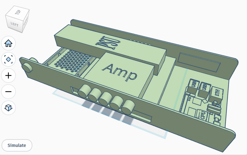
The rear panel is formed from a fold of the perforated steel and features cutouts for IEC 3 pin power supply (complete with fuse & isolation switch), 6x 4mm banana plugs for the speaker outputs, and a 3d printed keystone rack which allows for 4 keystone couplers to be mounted.
This is complete!
Electronics
This was a fun challenge and I learned about relays which turned out to be pretty valuable knowledge!
So firstly, a Raspberry Pi 5 requires somewhere around 25w (5v at 5a) via USB-C. There are various other ways you can power one, but this is the most straightforward.
The amplifier can accept 12-24v and, as I found while trying out different solutions, it sounds its best by quite some margin if you can give it 24v instead of 12v.
The reasons for this I’m not very well versed in other than being vaguely aware that some audio gear does better with more “headroom” in the context of guitar & bass effects pedals.
I also have alot of various USB-C power boards – some of them get concerningly hot so I do avoid using those, however I have a few USB-C PD boards which should be ideal for this. They can accept 5-30v and will negotiate power voltage with the connected device.
So with the ideal voltage for the amplifier, I figured finding a 24v power supply would be ideal, it could be connected directly to the amp and then all I need is a USB-C PD board to power the pi which can also be directly connected.
It does need to be small, ideally cheap, so I settled for a 24v PSU which is intended as an LED driver.
This cost £18 off scamazon and has two sets of outputs which is ideal, and it’s also a nice slim form factor which fits quite nicely in the case.
So I wired this up for the amp, and also with some amount of trial & error, used a relay module for the amp power supply which connects to a 5v GPIO pin on the pi.
This way, the amp follows the power state of the pi, so when I eventually get the front panel done & mount the power button, it should control the Pi which then controls the amplifier.
Leave a Reply